
1. Introduction
This document specifies the Open Audio Renderer (OAR) for rendering immersive audio content compliant with the Immersive Audio Model and Formats ([IAMF]) standard.The OAR specification provides the architecture and algorithms for the rendering of channel-based, scene-based, and object-based Audio Elements to various loudspeaker layouts and headphones. It further defines how to mix these Audio Elements and handle the animation and application of dynamic parameters, such as position and gain, provided by [IAMF] metadata. This specification also includes provisions for loudness normalization and peak limiting to be applied before final playback.
2. Immersive Audio (IA) Processing Architecture
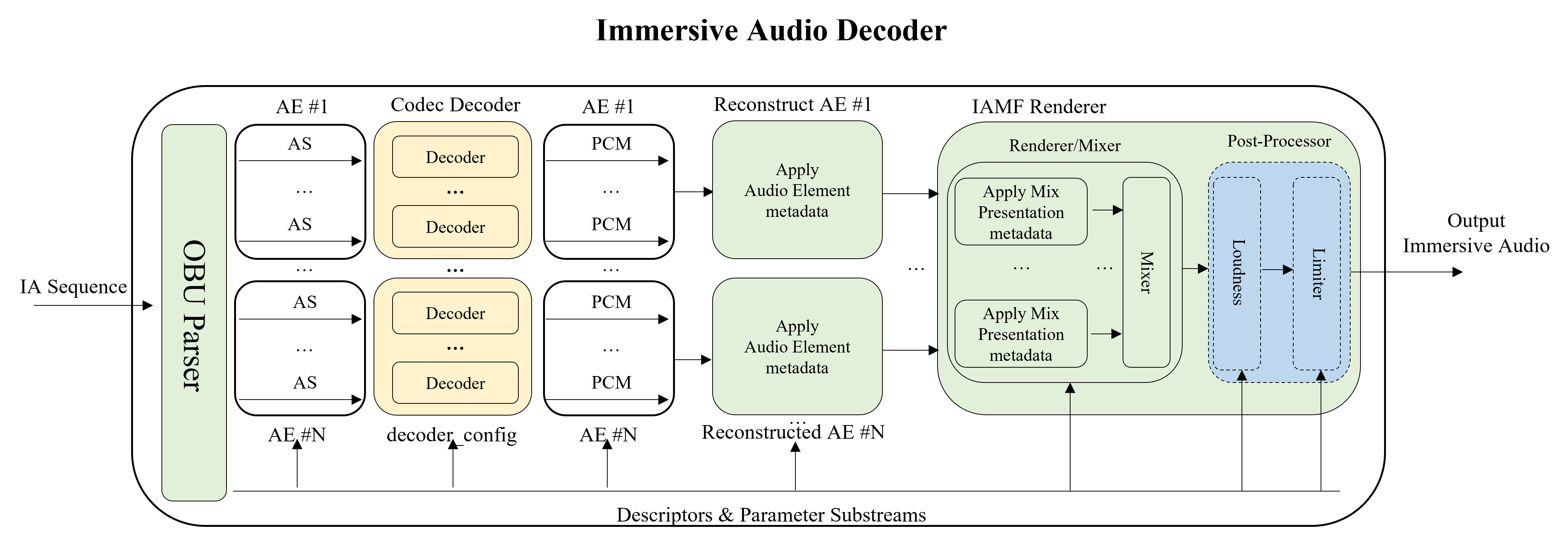
The Immersive Audio (IA) processing architecture includes two main components that process [IAMF]-compliant immersive audio content in sequence: the IAMF Decoder and the IAMF Renderer. The OAR specification defines the IAMF Renderer component. The IAMF Decoder is specified in [IAMF] and described here for background information only.The figure below depicts an example of the IA processing architecture.
IAMF Decoder
The IAMF Decoder is outside the scope of this specification. It consists of the OBU Parser, the Codec Decoder, and the Audio Element Reconstructor. For a given IA Sequence,
-
The OBU parser depacketizes the IA Sequence to output the Descriptors (including Mix Presentations), Audio Substreams and Parameter Substreams.
-
The Codec Decoder for each Audio Substream outputs the decoded channels.
-
The Audio Element Reconstructor reconstructs each Audio Element from the decoded channels.
IAMF Renderer
The IAMF Renderer is within the scope of this specification. It consists of the Renderer, the Mixer, and the Post-Processor. For a given Mix Presentation,
-
The Renderer renders each individually processed and reconstructed Audio Element to the playback layout.
-
The Mixer mixes the rendered Audio Elements using relevant mixing parameters.
-
The Post-Processor optionally applies loudness normalization and peak-limiting to the mixed audio before providing the final the Immersive Audio, i.e., the Rendered Mix Presentation for playback.
3. Open Audio Renderer (OAR)
The Open Audio Renderer (OAR) defines the IAMF Renderer component of the IA processing architecture. It uses renderer libraries such as the Open Loudspeaker Renderer (OLR) and the Open Binaural Renderer (OBR) to render Audio Elements. It provides rendering algorithms for three types of Audio Elements.-
CHANNEL_BASED
-
SCENE_BASED
-
OBJECT_BASED
It further provides an optional loudness processing module and an optional limiter for post processing the output audio signal after rendering and mixing.
3.1. OAR Structure
The modules in the OAR model defined by this specification are depicted in the figure below.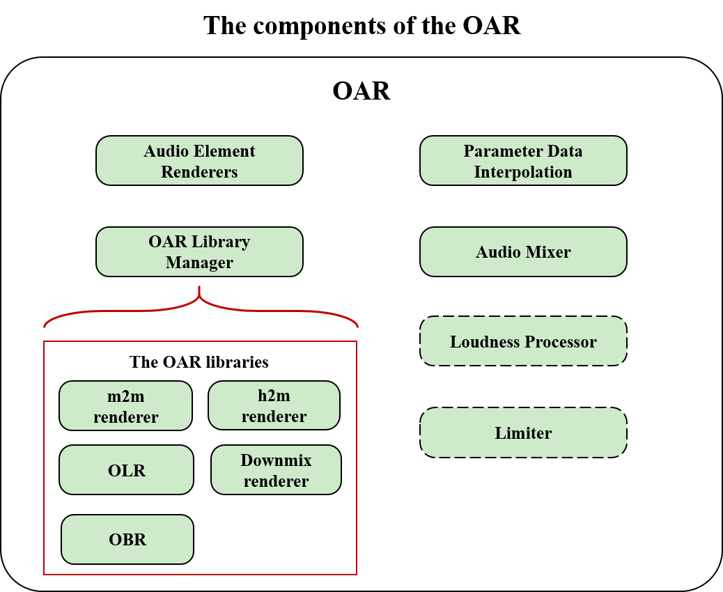
-
The Parameter Data Interpolation module applies rules described in § 6 Animated Parameters to convert input parameter metadata specified in AnimatedParameterData() into interpolated parameter data, which are used by the other modules.
-
The Audio Element Renderers modules consist of channel-based, scene-based, and object-based renderers. Each Audio Element Renderer renders an input Audio Element using its associated and interpolated parameter data using the OAR Libraries.
-
The OAR Library Manager manages the following OAR Libraries:
-
OLR (Open Loudspeaker Renderer)
-
OBR (Open Binaural Renderer)
-
EAR (EBU ADM Renderer), which includes the m2m renderer and h2m renderer
-
Downmix Renderer, which uses demix parameters
-
-
The Audio Mixer applies its associated and interpolated parameter data (element_mix_gain and element_gain_offset) to each rendered Audio Element, and then sums the Audio Elements with its associated and interpolated parameter data (output_mix_gain) applied for each sub-mix.
-
The Loudness Processor applies loudness normalization. It MAY be enabled or disabled.
-
The Limiter is used to limit the true peak of an audio signal. It MAY be enabled or disabled.
3.1.1. OAR Configuration
The following inputs are REQUIRED to configure OAR. The exception is target_loudness, which is only REQUIRED when the Loudness Processor module is enabled.
| OAR Configuration: | Description |
|---|---|
| target_layout: | Indicates the output layout used for rendering Audio Elements. Supported layouts are specified by sound_system in the [IAMF] specification. |
| frame_size: | Indicates the frame length, in samples, of the input Audio Elements. |
| sampling_rate: | Indicates the sample rate of the input Audio Elements in Hz. |
| target_loudness (Optional): | Indicates the target output level for loudness normalization, as specified in § 7.1 Loudness Normalization. |
3.1.1.1. Parameter Data Interpolation
The Parameter Data Interpolation module requires Parameter Block OBU information such as ParamDefinition() (including parameter_rate and subblock_duration) and AnimatedParameterData() (including gain and position). It then generates interpolated parameter data used by the Audio Element Renderers and Audio Mixer modules.
3.1.1.2. Audio Element Renderers
The Audio Element Renderers REQUIRE the following configuration and parameters to render an input Audio Element:
-
If audio_element_type = CHANNEL_BASED
-
loudspeaker_layout is REQUIRED to indicate the channel layout of the input Audio Element.
-
The multichannel input Audio Element is expected to be in planar format with the channels ordered according to the loudspeaker location ordering indicated by its loudspeaker_layout or expanded_loudspeaker_layout.
-
If parameter_flag = DOWNMIX_MODE
-
The DefaultDemixingInfoParameterData() or DemixingInfoParameterData() metadata is REQUIRED for OAR to select the appropriate down-mix matrices. For detailed information, refer to IAMF specification Demixing Information.
-
-
If parameter_flag = HEADPHONES_RENDERING_MODE
-
The headphones_rendering_mode is REQUIRED for OAR to decide whether the input CHANNEL_BASED Audio Element is rendered to stereo or spatialized with a binaural renderer when played back on headphones. For detailed information, refer to IAMF specification Headphone Rendering Mode.
-
-
-
If audio_element_type = SCENE_BASED
-
The Ambisonics order of the input Audio Element is REQUIRED.
-
The input Ambisonics Audio Element is expected to use the AmbiX format, which uses Ambisonics Channel Number (ACN) channel ordering and SN3D normalization, as defined in [ITU-2076-2].
-
The multichannel input Ambisonics Audio Element is expected to be in planar format.
-
-
If audio_element_type = OBJECT_BASED
-
num_objects is REQUIRED to indicate the number of objects in the input Audio Element. The number of objects is 1 or 2.
-
If num_objects = 1, the Audio Element has one channel of audio.
-
If num_objects = 2, the Audio Element has two channels of audio, one for each object. The multichannel input Audio Element is expected to be in planar format.
-
-
A referenced and interpolated position parameter data is REQUIRED.
-
If num_objects = 1, the interpolated position parameter data from its corresponding PolarParameterData(), Cart8ParameterData() or Cart16ParameterData() is REQUIRED.
-
If num_objects = 2, the interpolated position parameter data from its corresponding DualPolarParameterData(), DualCart8ParameterData() or DualCart16ParameterData() is REQUIRED.
-
-
| loudspeaker_layout | Channel Layout | Loudspeaker Location Ordering | Reference |
|---|---|---|---|
| 0 | Mono | C | |
| 1 | Stereo | L/R | Loudspeaker configuration for Sound System A (0+2+0) of [ITU-2051-3] |
| 2 | 5.1ch | L/R/C/LFE/Ls/Rs | Loudspeaker configuration for Sound System B (0+5+0) of [ITU-2051-3] |
| 3 | 5.1.2ch | L/R/C/LFE/Ls/Rs/Ltf/Rtf | Loudspeaker configuration for Sound System C (2+5+0) of [ITU-2051-3] |
| 4 | 5.1.4ch | L/R/C/LFE/Ls/Rs/Ltf/Rtf/Ltr/Rtr | Loudspeaker configuration for Sound System D (4+5+0) of [ITU-2051-3] |
| 5 | 7.1ch | L/R/C/LFE/Lss/Rss/Lrs/Rrs | Loudspeaker configuration for Sound System I (0+7+0) of [ITU-2051-3] |
| 6 | 7.1.2ch | L/R/C/LFE/Lss/Rss/Lrs/Rrs/Ltf/Rtf | The combination of 7.1ch and the Left and Right top front pair of 7.1.4ch |
| 7 | 7.1.4ch | L/R/C/LFE/Lss/Rss/Lrs/Rrs/Ltf/Rtf/Ltb/Rtb | Loudspeaker configuration for Sound System J (4+7+0) of [ITU-2051-3] |
| 8 | 3.1.2ch | L/R/C/LFE/Ltf/Rtf | The front subset (L/C/R/Ltf/Rtf/LFE) of 7.1.4ch |
| 9 | 9.1.6ch | FL/FR/FC/LFE1/BL/BR/FLc/FRc/SiL/SiR/TpFL/TpFR/TpBL/TpBR/TpSiL/TpSiR | The subset of Loudspeaker configuration for Sound System H (9+10+3) of [ITU-2051-3] |
| 10 | 10.2.9.3ch | FL/FR/FC/LFE1/BL/BR/FLc/FRc/BC/LFE2/SiL/SiR/TpFL/TpFR/TpFC/TpC/TpBL/TpBR/TpSiL/TpSiR/TpBC/BtFC/BtFL/BtFR | Loudspeaker configuration for Sound System H (9+10+3) of [ITU-2051-3] |
| 11 | 7.1.5.4ch | L/R/C/LFE/Lss/Rss/Lrs/Rrs/Ltf/Rtf/TpC/Ltb/Rtb/BtFL/BtFR/BtBL/BtBR | Loudspeaker configuration with the top and the bottom speakers added to Loudspeaker configuration for Sound System J (4+7+0) of [ITU-2051-3] |
| 12 | Binaural | L/R | |
| 13 | LFE | LFE | The low-frequency effects subset (LFE) of 7.1.4ch |
| 14 | Stereo-S | Ls/Rs | The surround subset (Ls/Rs) of 5.1.4ch |
| 15 | Stereo-SS | Lss/Rss | The side surround subset (Lss/Rss) of 7.1.4ch |
| 16 | Stereo-RS | Lrs/Rrs | The rear surround subset (Lrs/Rrs) of 7.1.4ch |
| 17 | Stereo-TF | Ltf/Rtf | The top front subset (Ltf/Rtf) of 7.1.4ch |
| 18 | Stereo-TB | Ltb/Rtb | The top back subset (Ltb/Rtb) of 7.1.4ch |
| 19 | Top-4ch | Ltf/Rtf/Ltb/Rtb | The top 4 channels (Ltf/Rtf/Ltb/Rtb) of 7.1.4ch |
| 20 | 3.0ch | L/R/C | The front 3 channels (L/C/R) of 7.1.4ch |
| 21 | Stereo-F | FL/FR | The front subset (FL/FR) of 9.1.6ch |
| 22 | Stereo-Si | SiL/SiR | The side subset (SiL/SiR) of 9.1.6ch |
| 23 | Stereo-TpSi | TpSiL/TpSiR | The top side subset (TpSiL/TpSiR) of 9.1.6ch |
| 24 | Top-6ch | TpFL/TpFR/TpBL/TpBR/TpSiL/TpSiR | The top 6 channels (TpFL/TpFR/TpSiL/TpSiR/TpBL/TpBR) of 9.1.6ch |
| 25 | LFE-Pair | LFE1/LFE2 | The low-frequency effects subset (LFE1/LFE2) of 10.2.9.3ch |
| 26 | Bottom-3ch | BtFC/BtFL/BtFR | The bottom 3 channels (BtFL/BtFC/BtFR) of 10.2.9.3ch |
| 27 | Bottom-4ch | BtFL/BtFR/BtBL/BtBR | The bottom 4 channels (BtFL/BtFR/BtBL/BtBR) of 7.1.5.4ch |
| 28 | Top-1ch | TpC | The top subset (TpC) of 7.1.5.4ch |
| 29 | Top-5ch | Ltf/Rtf/TpC/Ltb/Rtb | The top 5 channels (Ltf/Rtf/TpC/Ltb/Rtb) of 7.1.5.4ch |
3.1.1.3. Audio Mixer
For each referenced and rendered Audio Element to be mixed by the Audio Mixer, the corresponding referenced and interpolated element_mix_gain parameter data is REQUIRED. If the element gain offset mode is enabled, the referenced element_gain_offset is additionally REQUIRED.
For each sub-mix, a referenced and interpolated output_mix_gain parameter data mix is REQUIRED to be applied to the summed Audio Element.
3.1.1.4. Loudness Processor
If the Loudness Processor module is enabled, loudness metadata, including current loudness and target_loudness, is REQUIRED to perform loudness normalization.
3.1.2. Channel- and Scene-Based Renderers
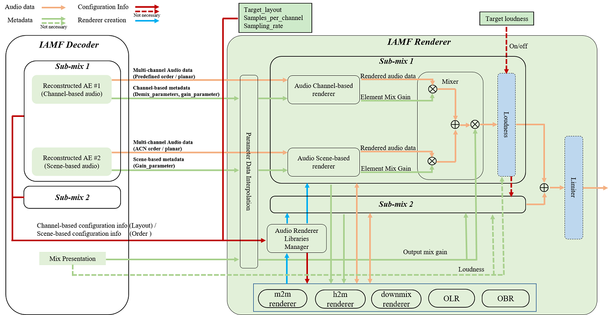
The IAMF Renderer receives Audio Elements, parameter data, and configuration information related to channel-based or scene-based audio from the IAMF Decoder, as detailed in § 3.1.1 OAR Configuration.Renderer libraries such as EAR (m2m renderer, h2m renderer) ([ITU-2127-0]), § 4.2 Rendering an Audio Element to Headphones and a downmix renderer with demix parameters are used to render the Audio Elements to the target_layout.
-
Rendering of channel-based Audio Element to loudspeakers is described in § 4.1.1 Channel-Based Audio Loudspeaker Rendering.
-
Rendering of channel-based Audio Element to headphones is described in § 4.2.1 Channel-Based Audio Binaural Rendering.
-
Rendering of scene-based Audio Element to loudspeakers is described in § 4.1.2 Scene-Based Audio Loudspeaker Rendering.
-
Rendering of scene-based Audio Element to headphones is described in § 4.2.2 Scene-Based Audio Binaural Rendering.
The rendered Audio Elements are mixed using the referenced mix gains, and the loudness and limiter logic MAY be selectively applied.
3.1.3. Object-Based Renderer
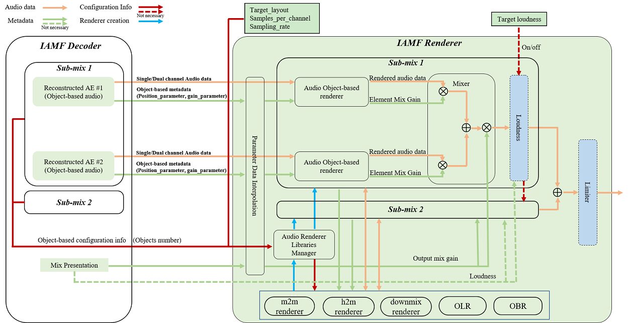
The IAMF Renderer receives Audio Elements, parameter data, and configuration information related to object-based audio from the IAMF Decoder, as detailed in § 3.1.1 OAR Configuration.Renderer libraries such as OLR and OBR are used to render the audio data.
-
Rendering of object-based Audio Element to loudspeakers is described in § 4.1.3 Object-Based Audio Loudspeaker Rendering.
-
Rendering of object-based Audio element to headphones is described in § 4.2.3 Object-Based Audio Binaural Rendering.
The rendered Audio Elements are mixed using the referenced mix gains, and the loudness and limiter logic MAY be selectively applied.
4. Rendering an Audio Element
This specification supports the rendering of either a channel-based, a scene-based, or an object-based Audio Element to either a target loudspeaker layout or binaurally, to headphones.If a preferred renderer is not signaled in [IAMF] bitstream, rendering to either the target loudspeaker or binaurally, to headphones SHALL be done using the default renderer, defined in sub-sections. Otherwise, rendering to either the target loudspeaker or binaurally, to headphones SHALL be done using either the default renderer or the preferred renderer.
In this section, for a given x.y.z layout, the next highest layout x'.y'.z' means that x', y', and z' are greater than or equal to x, y, and z, respectively.
audio_element_type
| Playback layout | Section |
|---|---|---|
| CHANNEL_BASED | Loudspeakers | § 4.1.1 Channel-Based Audio Loudspeaker Rendering |
| SCENE_BASED | Loudspeakers | § 4.1.2 Scene-Based Audio Loudspeaker Rendering |
| OBJECT_BASED | Loudspeakers | § 4.1.3 Object-Based Audio Loudspeaker Rendering |
| CHANNEL_BASED | Headphones | § 4.2.1 Channel-Based Audio Binaural Rendering |
| SCENE_BASED | Headphones | § 4.2.2 Scene-Based Audio Binaural Rendering |
| OBJECT_BASED | Headphones | § 4.2.3 Object-Based Audio Binaural Rendering |
This section and sub-sections are normative unless noted otherwise.
4.1. Rendering an Audio Element to Loudspeakers
This section defines the loudspeaker renderer, which is used as the default renderer to render an Audio Element to a loudspeaker playback layout.4.1.1. Channel-Based Audio Loudspeaker Rendering
This section defines the default renderer to use, given a channel-based Audio Element and a loudspeaker playback layout.22.2ch represents the Loudspeaker configuration for Sound System H (9+10+3).
-
The input layout (x.y.z) of the renderer SHALL be set as follows:
-
If loudspeaker_layout < 10, use the loudspeaker_layout of the Audio Element.
-
Else if loudspeaker_layout = 15,
-
If expanded_loudspeaker_layout = 1, use 5.1.4ch with empty channels everywhere other than the corresponding loudspeaker locations.
-
Else if expanded_loudspeaker_layout < 8, use 7.1.4ch with empty channels everywhere other than the corresponding loudspeaker locations.
-
Else if expanded_loudspeaker_layout = 13, use 22.2ch.
-
Else if expanded_loudspeaker_layout < 16, use 22.2ch with empty channels everywhere other than the corresponding loudspeaker locations except LFE2. LFE2 of 22.2ch is copied from LFE1.
-
Else if expanded_loudspeaker_layout < 20, use 7.1.5.4ch with empty channels everywhere other than the corresponding loudspeaker locations.
-
-
-
The output layout of the renderer SHALL be set to the playback layout (X.Y.Z).
-
The renderer SHALL be selected according to the following rules:
-
If DOWNMIX_MODE is off, render according to § 4.1.1.1 Rendering Without Demixing Info.
-
Else,
-
If the playback layout has height channels, use DemixingInfoParameterData() or DefaultDemixingInfoParameterData().
-
Else, if the input layout does not have height channels, use DemixingInfoParameterData() or DefaultDemixingInfoParameterData().
-
Else, use the EAR Direct Speakers renderer ([ITU-2127-0]).
-
-
4.1.1.1. Rendering Without Demixing Info
-
If the input layout is not 7.1.5.4ch,
-
If the playback layout is neither 3.1.2ch nor 7.1.2ch,
-
If the playback layout complies with the loudspeaker layouts supported by [ITU-2051-3], use the EAR Direct Speakers renderer ([ITU-2127-0]).
-
Else if the playback layout is 9.1.6ch,
-
If the input layout is 22.2ch, use the down-mix matrix specified in § 8.2 Static Down-mix Matrix.
-
Else, use the EAR Direct Speakers renderer ([ITU-2127-0]), to first render the input audio to 22.2ch, followed by copying LFE1 to LFE2 and followed by down-mixing from 22.2ch to 9.1.6ch by using the down-mix matrix specified in § 8.2 Static Down-mix Matrix.
-
-
Else if the playback layout is 7.1.5.4ch,
-
If the input layout is 22.2ch, use the down-mix matrix specified in § 8.2 Static Down-mix Matrix.
-
Else, use the EAR Direct Speakers renderer ([ITU-2127-0]), to first render the input audio to 22.2ch, followed by down-mixing from 22.2ch to 7.1.5.4ch by using the down-mix matrix specified in § 8.2 Static Down-mix Matrix.
-
-
Else, an implementation-specific renderer can be used, for example.
-
-
Else if the playback layout is 7.1.2ch,
-
Use the EAR Direct Speakers renderer ([ITU-2127-0]), to first render the input audio to 7.1.4ch, followed by down-mixing from 7.1.4ch to 7.1.2ch. The height channels of 7.1.4ch are down-mixed to the height channels of 7.1.2ch as follows:
\[ \text{Ltf2} = \text{Ltf4} + 0.707 \times \text{Ltb} \]
\[ \text{Rtf2} = \text{Rtf4} + 0.707 \times \text{Rtb} \]
-
-
Else (i.e., the playback layout is 3.1.2ch),
-
If the input layout has height channels,
-
If the input layout is 22.2ch, use the EAR Direct Speakers renderer ([ITU-2127-0]), to first render the input audio to 7.1.4ch, followed by down-mixing from 7.1.4ch to 3.1.2ch by using the down-mix matrix specified in § 8.2 Static Down-mix Matrix.
-
Else, the static down-mix matrices specified in § 8.2 Static Down-mix Matrix are used.
-
-
Else if the surround channels (x) of the input layout > 3, the static down-mix matrices specified in § 8.2 Static Down-mix Matrix after inserting empty height channels into the input audio are used.
-
Else, empty channels are padded to the input audio relevant to the input layout to make 3.1.2ch. In that case, Mono is regarded as a Centre channel.
-
-
-
Else (i.e., the input layout is 7.1.5.4ch)
-
If the playback layout is 22.2ch, use the EAR Direct Speakers renderer ([ITU-2127-0]) Table 16 with added mapping rules for the bottom layer back speakers (B+/-135). The mapping rules for the bottom layer back speakers mirror the top layer back speakers (U+/-135) mapping rules (let’s call this render_7.1.5.4ch_to_22.2ch).
-
Else if the playback layout complies with the loudspeaker layouts supported by [ITU-2051-3], use render_7.1.5.4ch_to_22.2ch and followed by down-mixing from 22.2ch to the playback layout by using the same method defined in this specification.
-
Else if the playback layout is 7.1.2ch or 3.1.2ch, use render_7.1.5.4ch_to_22.2ch to first render the input audio to 22.2ch and followed by down-mixing from 22.2ch to the playback layout by using the same method defined in this specification.
-
Else if the playback layout is 7.1.5.4ch, render as it is.
-
Else, an implementation-specific renderer can be used.
-
4.1.1.2. Configuring the EAR Direct Speakers Renderer
If the EAR Direct Speakers renderer is used, the following SHALL be provided for each audio channel of the Audio Element:
-
speaker label: the label of the speaker position, using the same convention as SP Label in [ITU-2051-3]. This is defined for each audio channel of the Audio Element based on the information from loudspeaker_layout.
In [ITU-2051-3], an LFE audio channel can be identified either by an explicit label or its frequency content. In this specification, the LFE channel SHALL be identified based on the explicit label only, given by loudspeaker_layout.
4.1.2. Scene-Based Audio Loudspeaker Rendering
This section defines the default renderer to use, given a scene-based Audio Element and a loudspeaker playback layout.-
The input layout of the renderer SHALL be set to Ambisonics.
-
The output layout of the renderer SHALL be set to the playback layout.
-
The renderer used SHALL be selected according to the following rules:
-
If the playback layout complies with the loudspeaker layouts supported by [ITU-2051-3], use the EAR HOA renderer ([ITU-2127-0]).
-
Else, if the playback layout is 9.1.6ch, use the EAR HOA renderer ([ITU-2127-0]), to first render the input audio to 22.2ch, followed by down-mixing from 22.2ch to 9.1.6ch by using the down-mix matrix specified in § 8.2 Static Down-mix Matrix.
-
Else, if the playback layout is 7.1.5.4ch, use the EAR HOA renderer ([ITU-2127-0]), to first render the input audio to 22.2ch, followed by down-mixing from 22.2ch to 7.1.5.4ch by using the down-mix matrix specified in § 8.2 Static Down-mix Matrix.
-
Else, if there is an implementation-specific renderer, use it.
-
Else, use the EAR HOA renderer to render to the next highest [ITU-2051-3] layout compared to the playback layout, and then down-mix using an implementation-specific renderer or use the static down-mix matrices specified in § 8.2 Static Down-mix Matrix if available.
-
If the EAR HOA renderer is used, the following metadata SHALL be provided to the renderer for each audio channel:
-
Ambisonics order
-
Ambisonics degree
-
Ambisonics normalization method
The AmbiX format uses ACN channel ordering and SN3D normalization, defined in [ITU-2076-2]. Accordingly, the Ambisonics order and degree are computed from the channel index \(k\) as follows:
\[ \begin{aligned}[c] \text{order} \qquad & n = \left\lfloor{\sqrt{k}}\right\rfloor\\ \text{degree} \qquad & m = k - n \times (n + 1) \end{aligned} \]
4.1.3. Object-Based Audio Loudspeaker Rendering
This section defines the default renderer to use, given an object-based Audio Element and a loudspeaker playback layout (i.e., target layout).-
If the number of objects in the Audio Element is 2, the referenced dual position parameter data (DualPolarParameterData(), DualCart8ParameterData(), or DualCart16ParameterData()) SHALL be separated into two single position parameter data (PolarParameterData(), Cart8ParameterData(), or Cart16ParameterData()).
-
The single position parameter data SHALL be interpolated before rendering such that the rendered effect is perceptually equivalent to the result obtained by interpolation according to § 6 Animated Parameters.
-
Each object audio SHALL be rendered to the playback layout by using its associated and interpolated single position parameter data.
Open Loudspeaker Renderer (OLR) SHALL be used as the default renderer to render an object audio by using its associated and interpolated single position parameter data to the playback layout.
-
If the type of the position parameter data is Cartesian, the cartesian coordinates (x, y, z) SHALL be converted to polar coordinates (azimuth, elevation, distance) according to position conversion of ([ITU-2127-0]).
-
If the type of the position parameter data is already Polar, the polar coordinates (azimuth, elevation, distance) SHALL be used directly without conversion.
The figure below shows the OLR structure. The OLR receives an object audio and its associated polar coordinates (azimuth, elevation, distance), and renders the object audio to the target layout (i.e., outputs a rendered audio data).
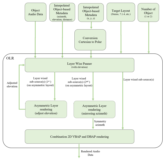
The OLR (also referred to as Layer-Wise Spatial Audio Rendering) consists of three algorithms, Layer-Wise Panning, 2D Asymmetric Layer Rendering, and Combination of 2D VBAP and DBAP Rendering. For a given object audio, its associated polar coordinates (azimuth, elevation, distance), and a target layout, it is processed as follows:
-
Step1: Layer-Wise Panning:
-
It takes as inputs an Object Source (the object audio or an Object Subsource in Step2), its associated polar coordinates, and the target layout.
-
It outputs one or two Object Subsources with their associated and updated polar coordinates based on the Object Source Elevation and the Target Layout Elevations. For more details, refer to § 4.1.3.1.1 Layer-Wise Panning.
-
\(\begin{aligned} &\text{object_subsource} \\ &\quad = \text{object_source} \times \text{LayerWiseGain(object_source_elevation, target_layout_elevation)} \end{aligned}\)
-
Where, for a given layer, LayerWiseGain means a gain computed based on the Object Source Elevation and the Target Layout Elevation for the layer.
-
-
-
Step2-A: 2D Asymmetric Layer Rendering
-
After applying Step1, if an Object Subsource exists in an asymmetric layer (e.g., only two speakers in the upper layer for 7.1.2 layout of [IAMF]), it is processed according to the § 4.1.3.1.2 2D Asymmetric Layer Rendering.
-
Otherwise, go to Step2-B.
-
-
Step2-B: Combination of 2D VBAP and DBAP Rendering
-
An Object Subsource on a specific layer is distributed to the speakers through a combination of VBAP and DBAP by using its associated and updated polar coordinates. To apply VBAP and DBAP, the Object Subsource is divided into a VBAP Subsource and a DBAP Subsource. For more details, refer to § 4.1.3.1.3 Combination of 2D VBAP and DBAP Rendering.
-
\(\begin{aligned} &\text{target_layout_speaker_gain} \\ &\quad = \text{VbapGain(vbap_subsource_position, target_layout_speaker_position)} \\ &\quad + \text{DbapGain(dbap_subsource_position, target_layout_speaker_position)} \end{aligned}\)
-
Where, for a given speaker position, VbapGain means a gain computed based on the position of the VBAP Subsource and the speaker position, and DbapGain means a gain computed based on the position of the DBAP Subsource and the speaker position.
-
-
4.1.3.1. Layer-Wise Spatial Audio Rendering
4.1.3.1.1. Layer-Wise Panning
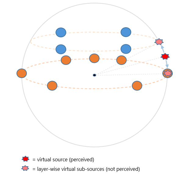
Each horizontal plane of a 3D loudspeaker layout is treated independently with a 2D rendering algorithm. In the Layer-Wise Panning, an Object Source (an object audio) is separated into one or two Object Subsources based on one or two adjacent 2D layers by applying a gain based on the elevation difference to each layer, respectively. When the layer-wise panning is applied to the Object Source, the Object Source Elevation and the Target Layout Elevations are REQUIRED.-
The term Object Source Elevation means the elevation of an Object Source.
-
The term Target Layout Elevation means the elevation of a layer of an target layout, defined in [ITU-2051-3] (e.g., Middle layer elevation = 0 and Upper layer elevation = +30 for 7.1.4ch).
For a given Object Source, its associated polar coordinates, and a target layout, the procedure is as follows (Examples - 7.1.4 Layout of [ITU-2051-3] for Middle layer elevation = 0, Upper layer elevation = +30):
-
If the Object Source Elevation is the same as a Target Layout Elevation, the Object Source is allocated directly to the corresponding layer as the Object Subsource.
-
If Object Source Elevation == Upper layer elevation (+30), apply 0dB gain of the Object Source to the upper layer of the target layout.
-
If Object Source Elevation == Middle layer elevation (0), apply 0dB gain of the Object Source to middle layer of an target layout.
-
-
Else if the Object Source Elevation is greater than the maximum elevation of the Target Layout Elevations or less than the minimum elevation of the Target Layout Elevationss of the target layout, the Object Source is allocated directly to the nearest layer as the Object Subsource and the elevation of the polar coordinates is updated to the elevation of the nearest layer.
-
If Object Source Elevation > Upper layer elevation (+30), apply 0dB gain of the Object Source to the upper layer of the target layout.
-
If Object Source Elevation < Middle layer elevation (0), apply 0dB gain of the Object Source to the middle layer of the target layout.
-
-
Else, the Object Source is separated into the Object Subsources and distributed to the two adjacent layers based on the elevation difference. The elevation of the polar coordinates for each Object Subsource is updated to the elevation of its associated layer of the target layout.
-
If Object Source Elevation < Upper layer elevation (+30) and Object Source Elevation > Middle layer elevation (0), apply a gain to each adjacent Upper and Middle layer. A standard pairwise panning algorithm, such as the tangent law can be used.
-
4.1.3.1.2. 2D Asymmetric Layer Rendering
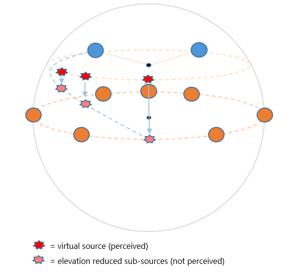
2D Asymmetric Layer Rendering defines the method to render an Object Subsource located in an asymmetric layout with no rear speakers. For example in the 7.1.2 layout, the height layer is asymmetric with 2 front speakers.If only the 2D layer is used and there is no rear speakers, the Object Subsource is allocated to the front speakers.
To express the sound of the back side, allocate a part of the Object Subsource to another layer with a rear speaker by reducing the elevation ratio.
-
The term Asymmetric Layer Speakers means the asymmetric layer speaker set of an target layout. (e.g., only two speakers in the upper layer for 7.1.2 layout of [IAMF]).
The procedure is as follows (Examples - 7.1.2 Layout of [IAMF] for two upper layer speakers U+045 and U-045):
-
If the Object Subsource azimuth exists within the azimuths (-45° <= azimuth <= 45°) of the Asymmetric Layer Speakers, the Object Subsource elevation is not changed and is rendered within the asymmetric layer itself.
-
If the Object Subsource azimuth exists outside the azimuth range (45° < azimuth < 315°) of the Asymmetric Layer Speakers, the Object Subsource elevation is proportionally reduced toward the adjacent layer.
-
For the Object Subsource with reduced elevation, Layer-Wise Panning is reapplied to adjacent layers as a Second Object Subsource.
-
At azimuth=180°, the Object Subsource is fully rendered with the adjacent layer as the Second Object Subsource.
-
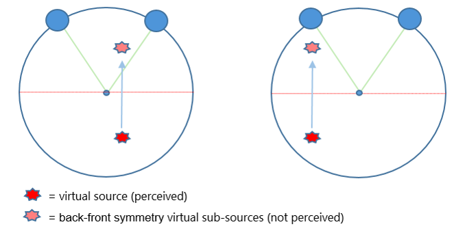
A method for applying VBAP and DBAP to the Second Object Subsource remaining in the asymmetric layer after partially allocated to adjacent layers. Within a single asymmetric layer, which includes two or one speakers, there is the Second Object Subsource for which 2D VBAP cannot be applied. In cases where only front speakers exist without rear speakers, the Second Object Subsource located at the back SHALL be assigned to the front speakers using combination of VBAP and DBAP.
-
If the Second Object Subsource exists on the front side (-90° < azimuth < 90°)
-
If the front side Second Object Subsource azimuth exists within the azimuths of the Asymmetric Layer Speakers, apply VBAP gains to the speakers.
-
If the front side Second Object Subsource azimuth exists outside the azimuth range of the Asymmetric Layer Speakers, apply VBAP directly to the adjacent speakers.
-
Apply DBAP gains according to the distance between the Second Object Subsource and all speakers.
-
-
If the Second Object Subsource exists on the back side (90° < azimuth < 270°), the Second Object Subsource is mirrored to the front using back-front symmetry to apply VBAP.
-
If the front side mirrored Second Object Subsource azimuth exists within the azimuths of the Asymmetric Layer Speakers, apply VBAP gains to the speakers.
-
If the front side mirrored Second Object Subsource azimuth exists outside the azimuth range of the Asymmetric Layer Speakers, apply VBAP directly to the adjacent speakers.
-
Apply DBAP gains according to the distance between the Second Object Subsource and all speakers.
-
4.1.3.1.3. Combination of 2D VBAP and DBAP Rendering
Combination of 2D VBAP and DBAP Rendering defines the algorithm effectively combining the direction of [VBAP] with the spatial diffusion of [DBAP] by utilizing three distinct zones, enabling more expressive elevation control.The term VBAP (Vector Base Amplitude Panning)
-
Applies gains to adjacent two speakers on the same layer based on azimuth of the Object SubSource, always applied at unit distance 1.
-
The VBAP method is used to emphasize the direction of the Object SubSource.
The term DBAP (Distance-Based Amplitude Panning)
-
Applies gains to all speakers on the same layer based on distance to the Object Subsource.
-
The DBAP method is used to express the direction and distance of the Object SubSource.
The Object Subsource is divided into a VBAP Subsource for applying the VBAP method and a DBAP Subsource for applying the DBAP method. Finally, the VBAP Subsource and the DBAP Subsource are distributed to the speakers in the current layer of the target layout. The desired position of the object is expressed by combining the VBAP Subsource and the DBAP Subsource. The Object Subsource has the position (azimuth, elevation, distance), where the elevation is the same as the current layer elevation of the Target Layout Elevations.
-
Separate VBAP Subsource
-
The VBAP Subsource is always positioned at a distance = 1 and has the same azimuth as the Object Subsource.
-
Performs panning considering only azimuth.
-
-
Separate DBAP Subsource
-
The DBAP Subsource has the same azimuth as the Object Subsource.
-
The distance values are recalculated according to the Object Subsource distance on the 3 zones.
-
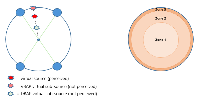
The gains of the separated VBAP Subsource and DBAP Subsource and the distance of the DBAP Subsource are calculated differently according to the three zones.
When the object subsource crosses the boundary of a zone, continuity is preserved to achieve a smooth and natural transition.
-
Zone 1 (distance < 0.5)
-
The DBAP Subsource is fixed at distance 0.
-
The VBAP Subsource is fixed at distance 1 and the VBAP Subsource gain gradually decreases as the Object Subsource distance decreases, increasing DBAP influence. As distance approaches 0, it gets closer to pure DBAP, and all speakers in the current layer of the target layout are activated.
-
-
Zone 2 (0.5 ≤ distance < 0.9)
-
The DBAP Subsource distance is calculated as "\(2 \times \text{object_subsource_distance} - 1\)" to position complementarily with the VBAP Subsource.
-
The DBAP Subsource and VBAP Subsource are combined using equal gains.
-
-
Zone 3 (distance ≥ 0.9)
-
The DBAP Subsource is fixed at distance 0.8.
-
The DBAP Subsource gain gradually decreases as distance increases, increasing VBAP influence.
-
When the Object Subsource distance is 1, the Object Subsource is positioned at the edge of the layout, and using pure VBAP.
-
4.2. Rendering an Audio Element to Headphones
This section defines Open Binaural Renderer (OBR), which is used as the default renderer to render an Audio Element to headphones.OBR is capable of rendering multiple Audio Elements. That is, only one instance of the renderer is REQUIRED to render all audio elements present in an IAMF sub-mix. Configuration of the renderer is done using its API. PCM audio data associated with all Audio Elements SHOULD be aggregated into a single audio buffer in planar format and processed using a single audio processing call to the renderer.
Sections § 4.2.1 Channel-Based Audio Binaural Rendering, § 4.2.2 Scene-Based Audio Binaural Rendering, and § 4.2.3 Object-Based Audio Binaural Rendering describe the operations associated with rendering of Channel-Based, Scene-Based, and Object-Based content repectively. Section § 4.2.4 OBR Core Processing Architecture describes the core architecture of OBR which is the same for all three types of content. Section § 4.2.5 Binaural Filter Profiles describes the binaural filter profiles supported by OBR.
4.2.1. Channel-Based Audio Binaural Rendering
Open Binaural Renderer SHALL be used as the default renderer to render channel-based Audio Elements to headphones.The rendering process operates as follows:
-
Each channel of the input Audio Element is encoded to Ambisonics using the predefined loudspeaker layout polar coordinates derived from the loudspeaker_layout. The azimuth and elevation are determined based on the speaker positions defined in [ITU-2051-3], and a distance of 1.0 is assumed for all channels.
-
Third-order Ambisonic (3OA) binaural filters are used for rendering the encoded Ambisonic representation to binaural stereo output.
-
The binaural filter profile SHALL be selected based on IAMF metadata. If not specified, the Ambient profile SHALL be used as the default. Available binaural filter profiles are described in § 4.2.5 Binaural Filter Profiles.
4.2.2. Scene-Based Audio Binaural Rendering
Open Binaural Renderer SHALL be used as the default renderer to render scene-based Audio Elements to headphones.The rendering process operates as follows:
-
Binaural filters with an Ambisonic order matching the order of the input scene-based Audio Element are used. The supported orders range from 1st to 4th order.
-
The binaural filter profile SHALL be selected based on IAMF metadata. If not specified, the Ambient profile SHALL be used as the default. Available binaural filter profiles are described in § 4.2.5 Binaural Filter Profiles.
-
If the input scene-based Audio Element is of 0th order, the single-channel signal SHALL be passed directly to both left and right output channels, bypassing binaural processing. In this case, the selection of binaural filter profile has no effect on the output.
4.2.3. Object-Based Audio Binaural Rendering
Open Binaural Renderer SHALL be used as the default renderer to render object-based Audio Elements to headphones.The rendering process operates as follows:
-
If the type of the position parameter data is Cartesian, the Cartesian coordinates (x, y, z) SHALL be converted to polar coordinates (azimuth, elevation, distance) according to position conversion of ([ITU-2127-0]).
-
If the type of the position parameter data is already Polar, the polar coordinates (azimuth, elevation, distance) SHALL be used directly without conversion.
-
Each object audio is encoded to Ambisonics using spherical harmonic encoding. The encoding matrices are computed based on the source directions (azimuth, elevation) and interpolated temporally to avoid artifacts during parameter changes.
-
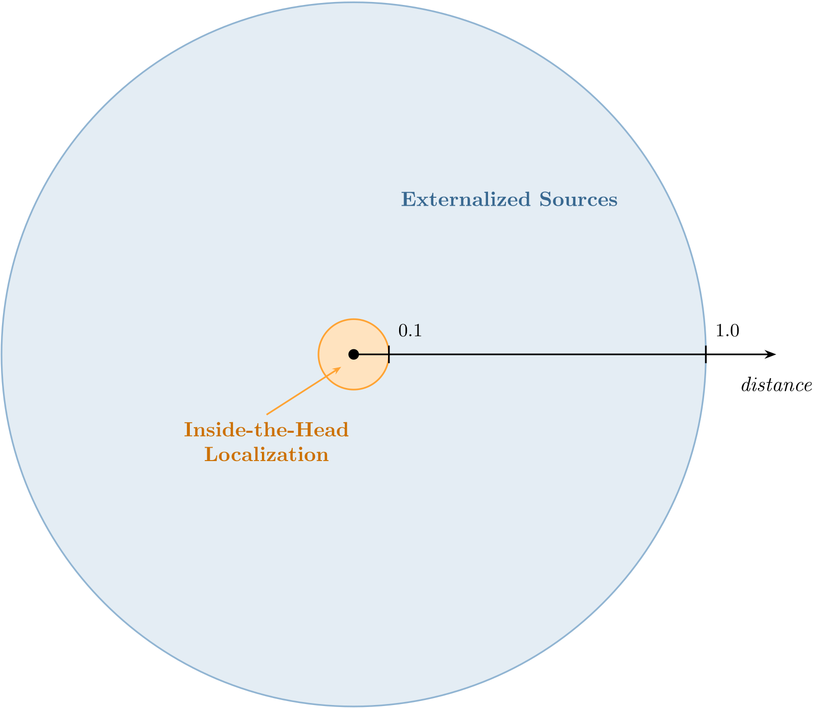
Distance handling is applied as follows:
-
Object distance values in the range of 0.1 to 1.0 are treated as 1.0. No distance-based processing is applied.
-
For object distance values less than 0.1, gradual attenuation of higher-order spherical harmonics is applied, introducing an inside-the-head localization effect.
-
-
Third-order Ambisonic (3OA) binaural filters are used for rendering the encoded Ambisonic representation to binaural stereo output.
-
The binaural filter profile SHALL be selected based on IAMF metadata. If not specified, the Ambient profile SHALL be used as the default. Available binaural filter profiles are described in § 4.2.5 Binaural Filter Profiles.
4.2.4. OBR Core Processing Architecture
OBR utilizes spherical harmonic (SH) representations of head-related impulse responses (HRIRs) and binaural room impulse responses (BRIRs) to enable efficient binaural rendering of channel-based, object-based, and Ambisonic content.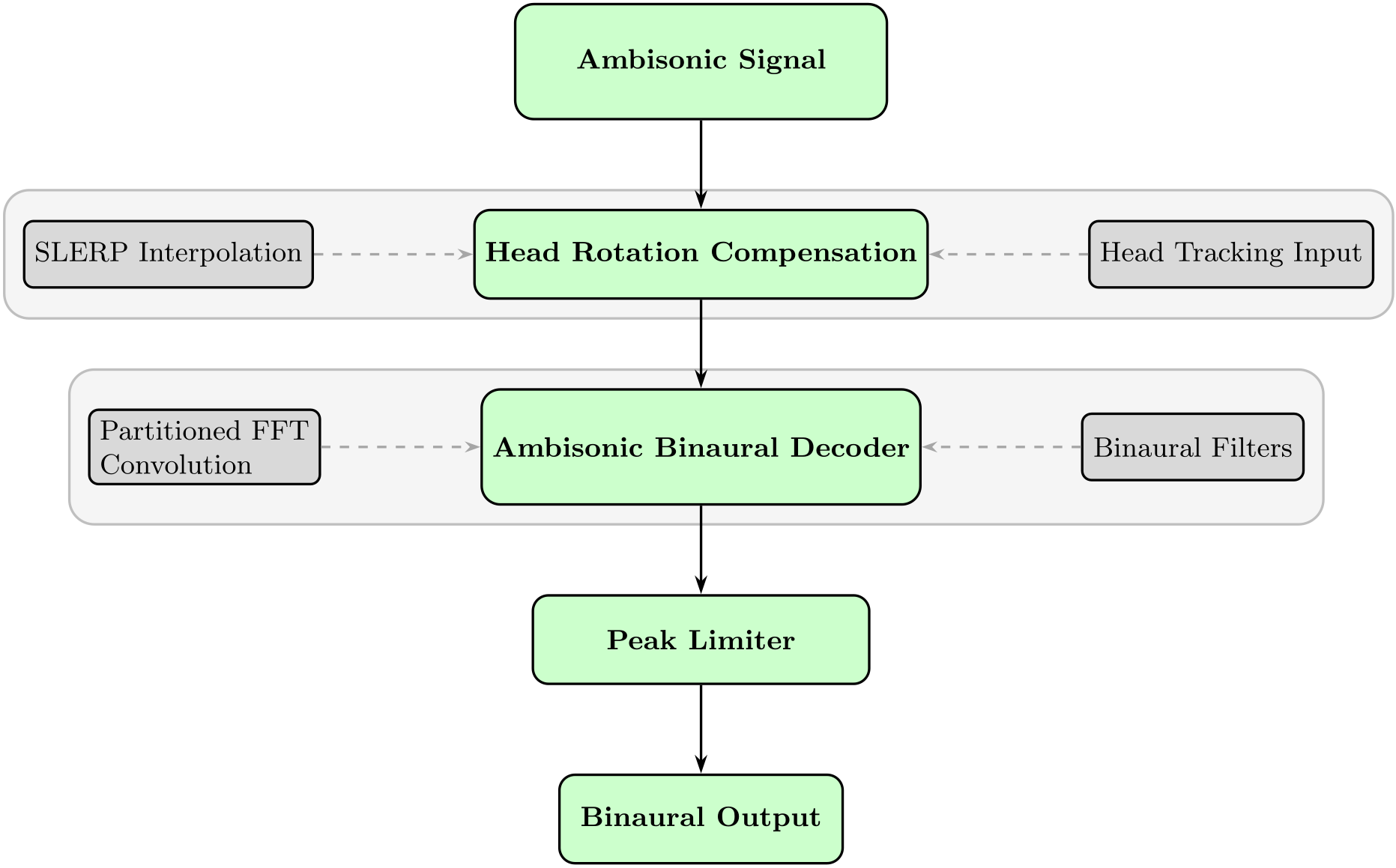
The renderer processes Ambisonic audio through the following stages:
-
Head Rotation Compensation — Accepts head-orientation data (as quaternions) to compensate for listener head rotation. Counter-rotation is applied to the Ambisonic bed using spherical harmonic rotation matrices, ensuring the spatial audio scene remains stable in world space.
-
Ambisonic Binaural Decoder — The Ambisonic signal is convolved with spherical harmonic-encoded IRs (SH-IRs) using partitioned FFT convolution for low-latency processing. Separate filter sets are maintained for left and right ears.
-
Peak Limiter — A peak limiter operates in linked stereo mode to prevent output clipping while preserving perceptual quality, with instantaneous attack and exponential release characteristics. The limiter MAY be disabled via API.
4.2.5. Binaural Filter Profiles
OBR provides three purposely tuned binaural filter profiles that SHALL be used for rendering Audio Elements. The profiles support Ambisonic orders from 1st to 4th order. The binaural filter coefficients for each profile are provided in the form of C++ code in the liboar GitHub repository.The profiles are as follows:
-
Direct — Uses anechoic HRIRs for precise localization and minimal coloration.
-
Ambient — Adds moderate room reflections, creating a natural sense of acoustic space. This is the RECOMMENDED default for general immersive content.
-
Reverberant — Incorporates stronger room response for content requiring enhanced spaciousness and externalisation.
5. Mixing Audio Elements
For a given Mix Presentation, after rendering all Audio Elements to a common playback layout, each Audio Element SHALL be processed individually before mixing as follows, where steps 3 and 4 MAY be applied in any order:-
If all Audio Elements do not have a common sample rate, re-sample them to a common sample rate. This specification RECOMMENDs 48 kHz.
-
If all Audio Elements do not have a common bit-depth, convert them to a common bit-depth. This specification RECOMMENDs using 16 bits.
-
Apply the per-element gain using the gain value specified in element_mix_gain.
-
If there are no element mix gain Parameter Block OBUs associated with the Audio Element, use the default_mix_gain value.
-
Else, use the param_data value provided in mix_gain_parameter_data.
-
-
Apply any per-element gain offset specified in element_gain_offset_config, if present.
-
If the element_gain_offset_type = VALUE, apply the element_gain_offset value.
-
Else if element_gain_offset_type = RANGE, apply a gain value within the range indicated by default_element_gain_offset, min_element_gain_offset and max_element_gain_offset such that the following are satisfied: \[ \text{gain} \le (\text{default_element_gain_offset} + \text{max_element_gain_offset}),\] \[ \text{gain} \ge (\text{default_element_gain_offset} + \text{min_element_gain_offset}).\]
-
The rendered and processed Audio Elements specified in one sub-mix of the Mix Presentation SHALL then be summed, and the output mix gain SHALL be applied using the value specified in output_mix_gain to generate one sub-mixed audio signal.
-
If there are no Parameter Block OBUs for the Parameter Substreams associated with the Mix Presentation, use the default_mix_gain value.
-
Else, use the param_data value provided in mix_gain_parameter_data.
If there are two sub-mixes in the Mix Presentation, the above processing SHALL be repeated to generate the other sub-mixed audio signal. The loudness of each sub-mixed audio signal is normalized according to the process defined in § 7.1 Loudness Normalization, and finally, the two audio signals SHALL be summed.
6. Animated Parameters
This section describes how a set of parameter values is animated over a subblock in a Parameter Block OBU using the information provided in AnimatedParameterData().The AnimatedParameterData() class provides a start point value for all animation_type values, either explicitly or implicitly. When animation_type is STEP, LINEAR or BEZIER, it is provided explicitly by start_point_value. When animation_type is INTER_LINEAR or INTER_BEZIER, it is provided implicitly and determined as follows.
-
The start point value is set to the default value defined in the associated parameter definition if one of the following is true:
-
this subblock is the first one in the Parameter Substream.
-
this subblock is the first one in the current parameter block and the previous parameter block is omitted from the previous Temporal Unit.
-
-
Otherwise, the start point value is derived from the previous subblock based on the previous subblock’s animation_type:
-
if animation_type is LINEAR, BEZIER, INTER_LINEAR or INTER_BEZIER, the start point value equals the end_point_value of the previous subblock.
-
if animation_type is STEP, the start point value equals the start_point_value of the previous subblock.
-
NOTE: If the animation_type of the first sublock accessed by IA decoders (e.g., in random access) is INTER_LINEAR or INTER_BEZIER, IA decoders might derive the start_point_value of the first subblock by decoding the Parameter Block OBU (if present) in the Temporal Unit indicated by audio_roll_distance. Otherwise, IA decoders might set the start_point_value to the corresponding default value defined in the associated parameter definition or the end_point_value of the first subblock.
Parameter values are defined in the parameter time domain but applied to audio samples in the audio time domain. Resampling from parameter time domain to audio time domain is performed relative to the start of the currently processed parameter block. For the current subblock being processed, the subblock start time, duration and end times are defined as below and expressed in parameter ticks at the parameter_rate given in the associated parameter definition.
-
Let \(t_{\text{start}}\) be the subblock start time relative to the start time of the current parameter block and \(t_{\text{start}}\) of the first subblock = 0. The start time of a parameter block is aligned with its decoding start time.
-
Let \(t_{\text{duration}} > 0\) be the subblock duration.
-
Let \(t_{\text{end}} = t_{\text{start}} + t_{\text{duration}}\) be the subblock end time (i.e., the next subblock start time).
These are mapped to the audio sample indices \(N_{\text{start}}\) and \(N_{\text{end}}\) as
\[ N_{\text{start}} = \left\lfloor \frac{t_{\text{start}} \times \text{audio_sample_rate}}{\text{parameter_rate}} \right\rfloor, \]
\[ N_{\text{end}} = \left\lfloor \frac{t_{\text{end}} \times \text{audio_sample_rate}}{\text{parameter_rate}} \right\rfloor. \]
6.1. animation_type = STEP
If animation_type is equal to STEP, the parameter value provided by start_point_value SHALL be applied to all time steps in the subblock.6.2. animation_type = LINEAR or INTER_LINEAR
If animation_type is equal to LINEAR or INTER_LINEAR, the set of parameter values is linearly interpolated. The exception is if its param_definition_type is equal to PARAMETER_DEFINITION_POLAR or PARAMETER_DEFINITION_DUAL_POLAR, in which case its interpolation method is described further below.
In the general linear interpolation case, compute the interpolation factor \(a\) at a given audio sample index \(n\) as
\[ a = \frac{n - N_{\text{start}}}{N_{\text{end}} - N_{\text{start}}}, \qquad 0 \le a \le 1. \]
The corresponding parameter value \(B_\text{linear}(a)\) to apply is
\[ B_{\text{linear}}(a) = (1 - a) \times \text{start_point_value} + a \times \text{end_point_value}. \]
If the param_definition_type is equal to PARAMETER_DEFINITION_POLAR or PARAMETER_DEFINITION_DUAL_POLAR, the distance value is interpolated as \(B_{\text{linear}}(a)\) and the azimuth and elevation angles are jointly interpolated along the shortest great-circle path on the unit sphere, using the spherical linear interpolation (slerp) method as follows.
If the start_point_values and end_point_values for both azimuth and elevation angles are identical, resulting in a subtended angle of 0, either endpoint may be used as the interpolated azimuth and elevation.
Otherwise, let \(\theta_{\text{start}}\) and \(\phi_{\text{start}}\) be the start_point_value of the azimuth and elevation angles respectively and converted to radians. They are then converted to a 3D Cartesian unit vector \(v_{\text{start}} = (v_{x0}, v_{y0}, v_{z0})\) as
\[ v_{x0} = \cos(\phi_{\text{start}}) \sin(-\theta_{\text{start}}), \]
\[ v_{y0} = \cos(\phi_{\text{start}}) \cos(-\theta_{\text{start}}), \]
\[ v_{z0} = \sin(\phi_{\text{start}}). \]
The end point unit vector \(v_{\text{end}}\) is similarly computed from the end_point_value of the azimuth and elevation angles.
The angle subtended by the arc is computed using the dot product as
\[ \Omega = \arccos(v_{\text{start}} \cdot v_{\text{end}}). \]
For a given interpolation factor \(a\), the interpolated 3D Cartesian vector along the arc, \(v(a) = \left(v_x(a), v_y(a), v_z(a)\right)\), is computed as
\[ v(a) = \frac{\sin((1-a)\Omega)}{\sin(\Omega)} v_{\text{start}} + \frac{\sin(a\Omega)}{\sin(\Omega)} v_{\text{end}}. \]
Finally, the interpolated vector is converted back to azimuth \(\theta(a)\) and elevation \(\phi(a)\) angles in radians as
\[ \theta(a) = -\text{atan2}(v_x(a), v_y(a)), \]
\[ \phi(a) = \arcsin(v_z(a)). \]
NOTE: \(\Omega\) can not be 180 degrees. Refer to [IAMF].
6.3. animation_type = BEZIER or INTER_BEZIER
If animation_type is equal to BEZIER or INTER_BEZIER, the information provided in AnimatedParameterData() combined with the timing information provided in ParamDefinition() and the Parameter Block OBU describe how the set of parameter values is animated as a quadratic Bezier curve.
In addition to mapping the subblock’s start and end times to audio sample indices \(N_{\text{start}}\) and \(N_{\text{end}}\), the subblock’s Bezier control point time is similarly mapped from parameter time domain. Let the control point time be
\[ t_{\text{ctrl}} = t_{\text{start}} + \text{round}(t_{\text{duration}} \times \text{control_point_relative_time}). \]
The value of \(t_{\text{ctrl}}\) is expressed in parameter ticks at the parameter_rate given in the assicated parameter definition.
The corresponding sample index is
\[ N_{\text{ctrl}} = \left\lfloor \frac{t_{\text{ctrl}} \times \text{audio_sample_rate}}{\text{parameter_rate}} \right\rfloor. \]
At a given audio sample \(n\), the mapping to the interpolation factor \(a\) (where \(0 \le a \le 1\)) is
\[ a = \begin{cases} -\frac{\gamma}{\beta}, & \text{if }~\alpha = 0,\\ \frac{-\beta + \sqrt{\beta^2 - 4 \alpha \gamma}}{2 \alpha} & \text{otherwise}, \end{cases} \]
where
\[ \alpha = n_{\text{start}} - 2 n_{\text{ctrl}} + n_{\text{end}}, \]
\[ \beta = 2(n_{\text{ctrl}} - n_{\text{start}}), \]
\[ \gamma = n_{\text{start}} - n. \]
The corresponding parameter value \(B_{\text{bezier}}(a)\) to apply is
\[ B_{\text{bezier}}(a) = (1 - a)^2 \times \text{start_point_value} + 2a(1 - a) \times \text{control_point_value} + a^2 \times \text{end_point_value}. \]
7. Post Processing
7.1. Loudness Normalization
Loudness normalization MAY be done by adjusting the loudness level to a target output level using the information provided in IAMF Mix Presentation Loudness. A control MAY be provided to set unique target output levels for each anchored loudness and/or the integrated loudness. If loudness normalization increases the output level, a peak limiter to prevent saturation and/or clipping MAY be necessary; true_peak or digital_peak SHOULD be used to determine if peak limiting is needed. Alternatively, the total amount of normalization MAY be limited.The rendered layouts that were used to measure the loudness information of a sub-mix are provided by loudness_layouts.
If one of them matches the playback layout, the loudness information SHOULD be used directly for normalization. If there is a mismatch between loudness_layout and the playback layout, the implementation MAY choose to use the provided loudness information of the highest loudness_layout as-is.
7.2. Limiter
The limiter MAY be used to limit the true peak of an audio signal at -1 dBTP, where the true peak is defined in [ITU-1770-4]. The limiter MAY be applied to multichannel signals in a linked manner and further support auto-release.8. Down-mix Matrix
8.1. Dynamic Down-mix Matrix
This specification provides dynamic down-mixing matrices generated by the down-mixing mechanism, which is specified in § 10.1 Annex A: Down-mix Mechanism.
8.2. Static Down-mix Matrix
This section provides static down-mix matrices to render to 3.1.2ch from 5.1.2ch, 5.1.4ch, 7.1.2ch, and 7.1.4ch, and to 9.1.6ch, 7.1.5.4ch from 22.2ch.Implementations MAY use a limiter defined in § 7.2 Limiter to preserve the energy of audio signals instead of using normalization factors.
The 3.1.2ch down-mix matrix for 5.1.2ch is given below, where \(p = 0.707\).
\[ \begin{bmatrix} \text{L3} \\ \text{C} \\ \text{R3} \\ \text{Ltf3} \\ \text{Rtf3} \\ \text{LFE} \end{bmatrix} = \begin{bmatrix} 1 & 0 & 0 & p & 0 & 0 & 0 & 0 \\ 0 & 1 & 0 & 0 & 0 & 0 & 0 & 0 \\ 0 & 0 & 1 & 0 & p & 0 & 0 & 0 \\ 0 & 0 & 0 & 0 & 0 & 1 & 0 & 0 \\ 0 & 0 & 0 & 0 & 0 & 0 & 1 & 0 \\ 0 & 0 & 0 & 0 & 0 & 0 & 0 & 1 \end{bmatrix} \times \begin{bmatrix} \text{L5} \\ \text{C} \\ \text{R5} \\ \text{Ls} \\ \text{Rs} \\ \text{Ltf2} \\ \text{Rtf2} \\ \text{LFE} \end{bmatrix} \]
The 3.1.2ch down-mix matrix for 5.1.4ch is given below, where \(p = 0.707\).
\[ \begin{bmatrix} \text{L3} \\ \text{C} \\ \text{R3} \\ \text{Ltf3} \\ \text{Rtf3} \\ \text{LFE} \end{bmatrix} = \begin{bmatrix} 1 & 0 & 0 & p & 0 & 0 & 0 & 0 & 0 & 0 \\ 0 & 1 & 0 & 0 & 0 & 0 & 0 & 0 & 0 & 0 \\ 0 & 0 & 1 & 0 & p & 0 & 0 & 0 & 0 & 0 \\ 0 & 0 & 0 & 0 & 0 & 1 & 0 & p & 0 & 0 \\ 0 & 0 & 0 & 0 & 0 & 0 & 1 & 0 & p & 0 \\ 0 & 0 & 0 & 0 & 0 & 0 & 0 & 0 & 0 & 1 \end{bmatrix} \times \begin{bmatrix} \text{L5} \\ \text{C} \\ \text{R5} \\ \text{Ls} \\ \text{Rs} \\ \text{Ltf4} \\ \text{Rtf4} \\ \text{Ltb} \\ \text{Rtb} \\ \text{LFE} \end{bmatrix} \]
The 3.1.2ch down-mix matrix for 7.1.2ch is given below, where \(p = 0.707\).
\[ \begin{bmatrix} \text{L3} \\ \text{C} \\ \text{R3} \\ \text{Ltf3} \\ \text{Rtf3} \\ \text{LFE} \end{bmatrix} = \frac{2}{1 + 2 \times p} \times \begin{bmatrix} 1 & 0 & 0 & p & 0 & p & 0 & 0 & 0 & 0 \\ 0 & 1 & 0 & 0 & 0 & 0 & 0 & 0 & 0 & 0 \\ 0 & 0 & 1 & 0 & p & 0 & p & 0 & 0 & 0 \\ 0 & 0 & 0 & 0 & 0 & 0 & 0 & 1 & 0 & 0 \\ 0 & 0 & 0 & 0 & 0 & 0 & 0 & 0 & 1 & 0 \\ 0 & 0 & 0 & 0 & 0 & 0 & 0 & 0 & 0 & 1 \end{bmatrix} \times \begin{bmatrix} \text{L7} \\ \text{C} \\ \text{R7} \\ \text{Lss} \\ \text{Rss} \\ \text{Lrs} \\ \text{Rrs} \\ \text{Ltf2} \\ \text{Rtf2} \\ \text{LFE} \end{bmatrix} \]
The 3.1.2ch down-mix matrix for 7.1.4ch is given below, where \(p = 0.707\).
\[ \begin{bmatrix} \text{L3} \\ \text{C} \\ \text{R3} \\ \text{Ltf3} \\ \text{Rtf3} \\ \text{LFE} \end{bmatrix} = \frac{2}{1 + 2 \times p} \times \begin{bmatrix} 1 & 0 & 0 & p & 0 & p & 0 & 0 & 0 & 0 & 0 & 0 \\ 0 & 1 & 0 & 0 & 0 & 0 & 0 & 0 & 0 & 0 & 0 & 0 \\ 0 & 0 & 1 & 0 & p & 0 & p & 0 & 0 & 0 & 0 & 0 \\ 0 & 0 & 0 & 0 & 0 & 0 & 0 & 1 & 0 & p & 0 & 0 \\ 0 & 0 & 0 & 0 & 0 & 0 & 0 & 0 & 1 & 0 & p & 0 \\ 0 & 0 & 0 & 0 & 0 & 0 & 0 & 0 & 0 & 0 & 0 & 1 \end{bmatrix} \times \begin{bmatrix} \text{L7} \\ \text{C} \\ \text{R7} \\ \text{Lss} \\ \text{Rss} \\ \text{Lrs} \\ \text{Rrs} \\ \text{Ltf4} \\ \text{Rtf4} \\ \text{Ltb} \\ \text{Rtb} \\ \text{LFE} \end{bmatrix} \]
The 9.1.6ch down-mix matrix for 22.2ch is given below, where \(p = 0.707\) and \(q = 0.5\). This down-mix matrix is generated based on Section 8.1 and Table 16 of [ITU-2127-0].
\[ \begin{bmatrix} \text{FLc} \\ \text{FC} \\ \text{FRc} \\ \text{FL} \\ \text{FR} \\ \text{SiL} \\ \text{SiR} \\ \text{BL} \\ \text{BR} \\ \text{TpFL} \\ \text{TpFR} \\ \text{TpSiL} \\ \text{TpSiR} \\ \text{TpBL} \\ \text{TpBR} \\ \text{LFE1} \end{bmatrix} = \begin{bmatrix} 1 & 0 & 0 & 0 & 0 & 0 & 0 & 0 & 0 & 0 & 0 & p & 0 & 0 & 0 & 0 & 0 & 0 & 0 & 1 & 0 & 0 & 0 & 0 \\ 0 & 1 & 0 & 0 & 0 & 0 & 0 & 0 & 0 & 0 & 0 & 0 & 0 & 0 & 0 & 0 & 0 & 0 & 0 & 0 & 1 & 0 & 0 & 0 \\ 0 & 0 & 1 & 0 & 0 & 0 & 0 & 0 & 0 & 0 & 0 & p & 0 & 0 & 0 & 0 & 0 & 0 & 0 & 0 & 0 & 1 & 0 & 0 \\ 0 & 0 & 0 & 1 & 0 & 0 & 0 & 0 & 0 & 0 & 0 & 0 & 0 & 0 & 0 & 0 & 0 & 0 & 0 & 0 & 0 & 0 & 0 & 0 \\ 0 & 0 & 0 & 0 & 1 & 0 & 0 & 0 & 0 & 0 & 0 & 0 & 0 & 0 & 0 & 0 & 0 & 0 & 0 & 0 & 0 & 0 & 0 & 0 \\ 0 & 0 & 0 & 0 & 0 & 1 & 0 & 0 & 0 & 0 & 0 & 0 & 0 & 0 & 0 & 0 & 0 & 0 & 0 & 0 & 0 & 0 & 0 & 0 \\ 0 & 0 & 0 & 0 & 0 & 0 & 1 & 0 & 0 & 0 & 0 & 0 & 0 & 0 & 0 & 0 & 0 & 0 & 0 & 0 & 0 & 0 & 0 & 0 \\ 0 & 0 & 0 & 0 & 0 & 0 & 0 & 1 & p & 0 & 0 & 0 & 0 & 0 & 0 & 0 & 0 & 0 & 0 & 0 & 0 & 0 & 0 & 0 \\ 0 & 0 & 0 & 0 & 0 & 0 & 0 & 0 & p & 1 & 0 & 0 & 0 & 0 & 0 & 0 & 0 & 0 & 0 & 0 & 0 & 0 & 0 & 0 \\ 0 & 0 & 0 & 0 & 0 & 0 & 0 & 0 & 0 & 0 & 1 & 0 & 0 & 0 & q & 0 & 0 & 0 & 0 & 0 & 0 & 0 & 0 & 0 \\ 0 & 0 & 0 & 0 & 0 & 0 & 0 & 0 & 0 & 0 & 0 & 0 & 1 & 0 & q & 0 & 0 & 0 & 0 & 0 & 0 & 0 & 0 & 0 \\ 0 & 0 & 0 & 0 & 0 & 0 & 0 & 0 & 0 & 0 & 0 & 0 & 0 & 1 & 0 & 0 & 0 & 0 & 0 & 0 & 0 & 0 & 0 & 0 \\ 0 & 0 & 0 & 0 & 0 & 0 & 0 & 0 & 0 & 0 & 0 & 0 & 0 & 0 & 0 & 1 & 0 & 0 & 0 & 0 & 0 & 0 & 0 & 0 \\ 0 & 0 & 0 & 0 & 0 & 0 & 0 & 0 & 0 & 0 & 0 & 0 & 0 & 0 & q & 0 & 1 & p & 0 & 0 & 0 & 0 & 0 & 0 \\ 0 & 0 & 0 & 0 & 0 & 0 & 0 & 0 & 0 & 0 & 0 & 0 & 0 & 0 & q & 0 & 0 & p & 1 & 0 & 0 & 0 & 0 & 0 \\ 0 & 0 & 0 & 0 & 0 & 0 & 0 & 0 & 0 & 0 & 0 & 0 & 0 & 0 & 0 & 0 & 0 & 0 & 0 & 0 & 0 & 0 & p & p \\ \end{bmatrix} \times \begin{bmatrix} \text{FLc} \\ \text{FC} \\ \text{FRc} \\ \text{FL} \\ \text{FR} \\ \text{SiL} \\ \text{SiR} \\ \text{BL} \\ \text{BC} \\ \text{BR} \\ \text{TpFL} \\ \text{TpFC} \\ \text{TpFR} \\ \text{TpSiL} \\ \text{TpC} \\ \text{TpSiR} \\ \text{TpBL} \\ \text{TpBC} \\ \text{TpBR} \\ \text{BtFL} \\ \text{BtFC} \\ \text{BtFR} \\ \text{LFE1} \\ \text{LFE2} \\ \end{bmatrix} \]
The 7.1.5.4ch down-mix matrix for 22.2ch is given below, where \(p = 0.707\). This down-mix matrix is generated based on Section 8.1 and Table 16 of [ITU-2127-0] with added mapping rules for the bottom layer back speakers (B+/-135). The mapping rules for the bottom layer back speakers mirror the top layer back speakers (U+/-135) mapping rules.
\[ \begin{bmatrix} \text{L} \\ \text{C} \\ \text{R} \\ \text{Lss} \\ \text{Rss} \\ \text{Lrs} \\ \text{Rrs} \\ \text{Ltf} \\ \text{Rtf} \\ \text{TpC} \\ \text{Ltb} \\ \text{Rtb} \\ \text{BtFL} \\ \text{BtFR} \\ \text{BtBL} \\ \text{BtBR} \\ \text{LFE} \\ \end{bmatrix} = \begin{bmatrix} 1 & 0 & 0 & p & 0 & 0 & 0 & 0 & 0 & 0 & 0 & 0 & 0 & 0 & 0 & 0 & 0 & 0 & 0 & 0 & 0 & 0 & 0 & 0 \\ 0 & 1 & 0 & 0 & 0 & 0 & 0 & 0 & 0 & 0 & 0 & 0 & 0 & 0 & 0 & 0 & 0 & 0 & 0 & 0 & 0 & 0 & 0 & 0 \\ 0 & 0 & 1 & 0 & p & 0 & 0 & 0 & 0 & 0 & 0 & 0 & 0 & 0 & 0 & 0 & 0 & 0 & 0 & 0 & 0 & 0 & 0 & 0 \\ 0 & 0 & 0 & p & 0 & 1 & 0 & 0 & 0 & 0 & 0 & 0 & 0 & 0 & 0 & 0 & 0 & 0 & 0 & 0 & 0 & 0 & 0 & 0 \\ 0 & 0 & 0 & 0 & p & 0 & 1 & 0 & 0 & 0 & 0 & 0 & 0 & 0 & 0 & 0 & 0 & 0 & 0 & 0 & 0 & 0 & 0 & 0 \\ 0 & 0 & 0 & 0 & 0 & 0 & 0 & 1 & p & 0 & 0 & 0 & 0 & 0 & 0 & 0 & 0 & 0 & 0 & 0 & 0 & 0 & 0 & 0 \\ 0 & 0 & 0 & 0 & 0 & 0 & 0 & 0 & p & 1 & 0 & 0 & 0 & 0 & 0 & 0 & 0 & 0 & 0 & 0 & 0 & 0 & 0 & 0 \\ 0 & 0 & 0 & 0 & 0 & 0 & 0 & 0 & 0 & 0 & 1 & p & 0 & p & 0 & 0 & 0 & 0 & 0 & 0 & 0 & 0 & 0 & 0 \\ 0 & 0 & 0 & 0 & 0 & 0 & 0 & 0 & 0 & 0 & 0 & p & 1 & 0 & 0 & p & 0 & 0 & 0 & 0 & 0 & 0 & 0 & 0 \\ 0 & 0 & 0 & 0 & 0 & 0 & 0 & 0 & 0 & 0 & 0 & 0 & 0 & 0 & 1 & 0 & 0 & 0 & 0 & 0 & 0 & 0 & 0 & 0 \\ 0 & 0 & 0 & 0 & 0 & 0 & 0 & 0 & 0 & 0 & 0 & 0 & 0 & p & 0 & 0 & 1 & p & 0 & 0 & 0 & 0 & 0 & 0 \\ 0 & 0 & 0 & 0 & 0 & 0 & 0 & 0 & 0 & 0 & 0 & 0 & 0 & 0 & 0 & p & 0 & p & 1 & 0 & 0 & 0 & 0 & 0 \\ 0 & 0 & 0 & 0 & 0 & 0 & 0 & 0 & 0 & 0 & 0 & 0 & 0 & 0 & 0 & 0 & 0 & 0 & 0 & 1 & p & 0 & 0 & 0 \\ 0 & 0 & 0 & 0 & 0 & 0 & 0 & 0 & 0 & 0 & 0 & 0 & 0 & 0 & 0 & 0 & 0 & 0 & 0 & 0 & p & 1 & 0 & 0 \\ 0 & 0 & 0 & 0 & 0 & 0 & 0 & 0 & 0 & 0 & 0 & 0 & 0 & 0 & 0 & 0 & 0 & 0 & 0 & 0 & 0 & 0 & 0 & 0 \\ 0 & 0 & 0 & 0 & 0 & 0 & 0 & 0 & 0 & 0 & 0 & 0 & 0 & 0 & 0 & 0 & 0 & 0 & 0 & 0 & 0 & 0 & 0 & 0 \\ 0 & 0 & 0 & 0 & 0 & 0 & 0 & 0 & 0 & 0 & 0 & 0 & 0 & 0 & 0 & 0 & 0 & 0 & 0 & 0 & 0 & 0 & p & p \\ \end{bmatrix} \times \begin{bmatrix} \text{FLc} \\ \text{FC} \\ \text{FRc} \\ \text{FL} \\ \text{FR} \\ \text{SiL} \\ \text{SiR} \\ \text{BL} \\ \text{BC} \\ \text{BR} \\ \text{TpFL} \\ \text{TpFC} \\ \text{TpFR} \\ \text{TpSiL} \\ \text{TpC} \\ \text{TpSiR} \\ \text{TpBL} \\ \text{TpBC} \\ \text{TpBR} \\ \text{BtFL} \\ \text{BtFC} \\ \text{BtFR} \\ \text{LFE1} \\ \text{LFE2} \\ \end{bmatrix} \]
Where FLc: Front Left Centre, FC: Front Centre, FRc: Front Right Centre, FL: Front Left, FR: Front Right, SiL: Side Left, SiR: Side Right, BL: Back Left, BC: Back Centre, BR: Back Right, TpFL: Top Front Left, TpFC: Top Front Cetnre, TpFR: Top Front Right, TpSiL: Top Side Left, TpC: Top Centre, TpSiR: Top Side Right, TpBL: Top Back Left, TpBC: Top Back Centre, TpBR: Top Back Right, BtFL: Bottom Front Left, BtFC: Bottom Front Centre, BtFR: Bottom Front Right, LFE1: Low-Frequency Effects-1, LFE2: Low-Frequency Effects-2, L: Left, C: Centre, R: Right, Lss: Left Side Surround, Rss: Right Side Surround, Lrs: Left Rear Surround, Rrs: Right Rear Surround, Ltf: Left Top Front, Rtf: Right Top Front, Ltb: Left Top Back, Rtb: Right Top Back, BtBL: Bottom Back Left, BtBR: Bottom Back Right, LFE: Low-Frequency Effects
9. Implementation Verification
All custom rendering and architecture modifications to OAR MUST adhere to the restrictions defined in this version of the specification.
Custom implementations and/or modifications to OAR, excluding the OLR or OBR renderers, MUST be verified using the IAMF conformance test vectors in conjunction with a compliant IAMF decoder.
Custom implementations and/or modifications to OLR or OBR only, excluding other OAR modules, SHOULD use ABX testing to validate perceptual parity with the reference OLR or OBR output. The ABX assessment SHOULD include listening test samples that emphasize the following attributes:
-
Timbral Coloration: The extent to which the sound is perceptually colored.
-
Envelopment: The perceived degree of being surrounded by the sound field.
-
Elevation: The degree to which the height or elevation of the sound is perceived.
-
Externalization: The degree to which sound is perceived as originating from outside the listener’s head.
-
Overall Audio Quality: An overall evaluation of all sound quality aspects, including but not limited to the attributes listed above.
10. Annex
10.1. Annex A: Down-mix Mechanism
This section specifies the down-mixing mechanism to generate down-mixed audio from an input channel-based rendered 3D audio signal.
For a given channel-based input 3D audio signal that conforms to the 7.1.4ch, the surround and top channels (if any) are separately down-mixed and especially step by step until to get the target channels.
Implementers can use another method to get the down-mixed audio from the given input 3D audio signal, as long as the down-mixed audio signal is the same as the result of what is described in this section.
A Down-Mixer based on the down-mix mechanism is a combination of the following surround Down-Mixer(s) and top Down-Mixer(s) as depicted in the figure below.
-
Surround Down-Mixers
-
S7to5 encoder: \[\text{Ls5} = \alpha(k) \times \text{Lss7} + \beta(k) \times \text{Lrs7}\] \[\text{Rs5} = \alpha(k) \times \text{Rss7} + \beta(k) \times \text{Rrs7}\]
-
S5to3 encoder: \[\text{L3} = \text{L5} + \delta(k) \times \text{Ls5}\] \[\text{R3} = \text{R5} + \delta(k) \times \text{Rs5}\]
-
S3to2 encoder: \[\text{L2} = \text{L3} + 0.707 \times \text{C}\] \[\text{R2} = \text{R3} + 0.707 \times \text{C}\]
-
S2to1 encoder: \[\text{Mono} = 0.5 \times (\text{L2} + \text{R2})\]
-
-
Top Down-Mixers
-
T4to2 encoder: \[\text{Ltf2} = \text{Ltf4} + \gamma(k) \times \text{Ltb4}\] \[\text{Rtf2} = \text{Rtf4} + \gamma(k) \times \text{Rtb4}\]
-
T2toTF2 encoder: \[\text{Ltf3} = \text{Ltf2} + w(k) \times \delta(k) \times \text{Ls5}\] \[\text{Rtf3} = \text{Rtf2} + w(k) \times \delta(k) \times \text{Rs5}\]
-
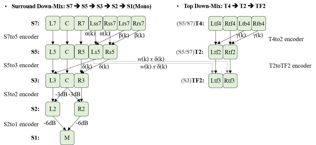
For example, to get the 3.1.2ch down-mixed audio from 7.1.4ch:
-
S3 of 3.1.2ch is generated by using S7to5 encoder and S5to3 encoder.
-
TF2 of 3.1.2ch is generated by using T4to2 encoder and T2toTF2 encoder.
10.2. Annex B: ID Linking Scheme (Informative)
The figure below shows the linking scheme among IDs in the obu_header or OBU payload.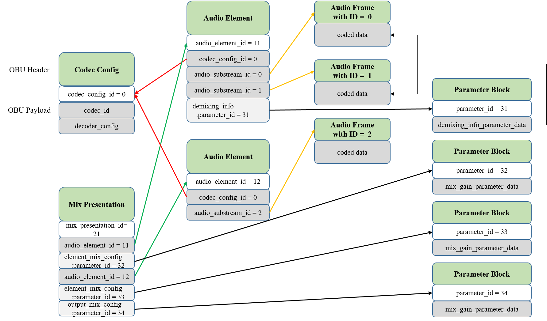
In the figure above,
-
The Codec Config OBU with codec_config_id = 0 is providing its codec_id and decoder_config.
-
The Mix Presentation OBU with mix_presentation_id = 21 is saying:
-
There are two Audio Elements (with audio_element_id = 11 and 12) which need to be mixed.
-
There are Parameter Block OBUs with parameter_id = 32 to be used for mixing the Audio Element with audio_element_id = 11.
-
There are Parameter Block OBUs with parameter_id = 33 to be used for mixing the Audio Element with audio_element_id = 12.
-
-
There are Parameter Block OBUs with parameter_id = 34 to be used for mixing the two Audio Elements.
-
-
The Audio Element OBU with audio_element_id = 11 is saying:
-
This Audio Element has been coded using the Codec Config OBU with codec_config_id = 0.
-
There are two Audio Substreams (audio_substream_id = 0 and 1, respectively) in this Audio Element. They are linked to the Audio Frame OBUs with audio_substream_id = 0 and audio_substream_id = 1 (i.e., obu_type = OBU_IA_Audio_Frame_ID0 and obu_type = OBU_IA_Audio_Frame_ID1), respectively.
-
There are Parameter Block OBUs with parameter_id = 31 to be used for demixing this Audio Element.
-
-
The Audio Element OBU with audio_element_id = 12 is saying:
-
This Audio Element has been coded by using the Codec Config OBU with codec_config_id = 0.
-
There is one Audio Substream (audio_substream_id = 2) in this Audio Element. It is linked to the Audio Frame OBUs with audio_substream_id = 2 (i.e., obu_type = OBU_IA_Audio_Frame_ID2).
-
-
The Audio Frame OBU with audio_substream_id = 0 (i.e., obu_type = OBU_IA_Audio_Frame_ID0) is providing the coded data which has been coded by using the Codec Config OBU with codec_config_id = 0.
-
The Audio Frame OBU with audio_substream_id = 1 (i.e., obu_type = OBU_IA_Audio_Frame_ID1) is providing the coded data which has been coded by using the Codec Config OBU with codec_config_id = 0.
-
The Audio Frame OBU with audio_substream_id = 2 (i.e., obu_type = OBU_IA_Audio_Frame_ID2) is providing the coded data which has been coded by using the Codec Config OBU with codec_config_id = 0.
-
The Parameter Block OBU with parameter_id = 31 is providing demixing_info_parameter_data to be applied for demixing the Audio Element with audio_element_id = 11.
-
The Parameter Block OBU with parameter_id = 32 is providing mix_gain_parameter_data to be applied to the rendered Audio Element after rendering according to rendering_config of the Audio Element with audio_element_id = 11.
-
The Parameter Block OBU with parameter_id = 33 is providing mix_gain_parameter_data to be applied to the rendered Audio Element after rendering according to rendering_config of the Audio Element with audio_element_id = 12.
-
The Parameter Block OBU with parameter_id = 34 is providing mix_gain_parameter_data to be applied to the Rendered Mix Presentation of the two rendered Audio Elements.